
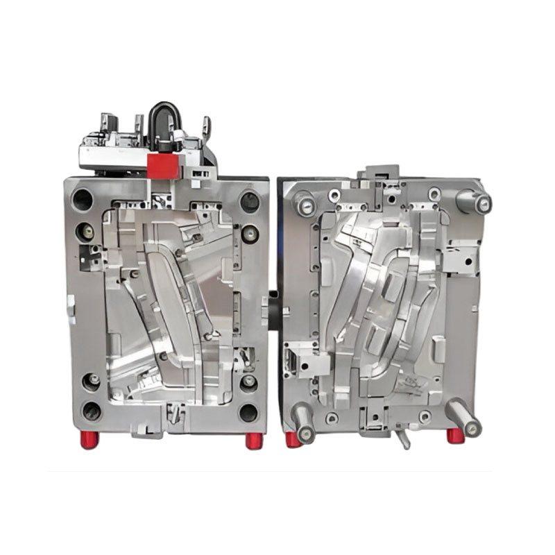


How to control the chip shape to improve machining stability during aluminum CNC turning?
Release Time : 2025-12-30
In aluminum CNC turning, controlling chip morphology is crucial for improving machining stability. Due to its softness and high toughness, aluminum easily forms long, continuous ribbon-like chips during cutting. These chips tend to entangle on the tool or workpiece, leading to machining interruptions, accelerated tool wear, and even dimensional errors, severely impacting machining stability. Therefore, effective control of chip morphology requires multi-dimensional optimization measures.
The tool geometry parameters are the primary factors affecting chip morphology in aluminum CNC turning. The rake angle directly affects the degree of chip deformation and flow direction. Increasing the rake angle reduces the contact area between the chip and the rake face, lowering friction and cutting temperature, resulting in thinner chips that are easier to curl. For example, using a large rake angle tool in aluminum CNC turning significantly reduces chip thickness, shrinks the curl radius, and improves chip breaking efficiency. The clearance angle affects flank wear and surface finish. During roughing, due to the heavy cutting load, a smaller clearance angle is needed to enhance heat dissipation; during finishing, the clearance angle can be appropriately increased to improve surface finish. Furthermore, adjusting the principal cutting edge angle and the tip radius can alter the chip flow path and cross-sectional shape, further optimizing the chip morphology.
Synergistic optimization of cutting parameters is the core method for controlling chip morphology. Increasing the feed rate directly leads to increased chip thickness. When the feed rate is small, the chips are long and ribbon-like, easily entangled. Appropriately increasing the feed rate can increase the transverse bending stress of the chips, causing them to fracture into short spirals or fragments. Cutting speed affects chip morphology by altering the temperature of the cutting zone. High-speed cutting significantly reduces material thermal softening, intensifying chip plastic deformation. However, excessively high cutting speeds may weaken the strain rate strengthening effect, increasing the difficulty of chip fracture. Depth of cut affects chip width and volume. A smaller depth of cut is beneficial for forming a compact chip morphology, but it needs to be dynamically balanced with the feed rate to avoid excessive chip volume leading to chip removal difficulties. For example, when milling titanium alloys, simultaneously adjusting the depth of cut and feed rate can maintain a reasonable chip morphology and prevent poor chip removal due to excessive single-tooth cutting load.
Tool structure innovation and material selection play a supporting role in chip control. Reducing the number of milling cutter teeth and increasing chip clearance can prevent chip clogging. For example, small-diameter milling cutters use a two-tooth design, and medium-diameter milling cutters use a three-tooth design to adapt to the high plasticity and large cutting deformation characteristics of aluminum. Coated tools (such as diamond coatings) can reduce aluminum chip adhesion, making chips easier to remove; helical flute designs prevent entanglement by promoting chip breaking. In addition, the geometric characteristics of the chip breaker (such as width, depth, and radius of curvature) are key to controlling chip curling and breakage. Properly designed chip breaker parameters can achieve stable formation of "C" or "6" shaped chips.
Improved cooling and lubrication conditions can indirectly affect chip morphology. Traditional emulsion cooling has limited penetration capacity and has little direct impact on chip breaking; high-pressure cooling technology promotes chip breakage through hydraulic impact. For example, using a tilted high-pressure nozzle in conjunction with high-pressure coolant can transform long ribbon-like chips into short helical shapes. Minimum Quantity Lubrication (MQL) technology improves chip morphology by reducing the coefficient of friction, decreasing chip adhesion to the rake face, and increasing chip breaking frequency.
Optimizing machining processes and operating strategies is equally important. Using intermittent "pecking" or segmented machining, and periodically retracting the tool, can help with chip removal. Setting retraction points in the CNC program and promptly clearing chips prevent entanglement. For deep hole machining, compressed air can be used to assist chip removal, or a drill-then-mill process can be adopted, drilling the tool hole first and then milling to solve the problem of poor chip removal caused by insufficient chip space in the milling cutter.
The dynamic performance of the machine tool and the workpiece clamping method are also crucial. The rigidity and stability of the machine tool directly affect vibration control during the cutting process; vibration can easily lead to uncontrolled chip morphology. When clamping the workpiece, the clamping force must be controlled to avoid deformation affecting chip formation. For example, releasing the clamping force before finishing to restore the part to its original shape and then lightly re-clamping it can reduce the interference of clamping deformation on chip morphology.